Foundation drainage is as integral a part of suburban construction as the construction of the foundation itself. Moreover, it must be said that in the abstract understanding of the foundation, as the basis of the future structure, without division into types and types, drainage exists in a multi-level mode with a two-sided approach to resolving the issue. Naturally, drainage work in this case goes in parallel with the waterproofing of the structure’s support. Also, we cannot write off earthworks, which play a very important role.
In the article we will consider three main types of foundations (from FBS building blocks, monolithic pouring and a solid-filled slab for frame houses) and methods of their drainage, taking into account auxiliary and related work.
FBS blocks
The classic version of the foundation, in which the blocks are located at a fairly decent depth. The individual structural elements are fastened together using a cement-sand mortar, which makes the connection itself vulnerable to excess moisture, and even more so in direct contact with water.
The soil drainage system around the foundation is carried out on two sides - external and internal. With the development of the modern construction industry, chemical agents began to appear that, in principle, are capable of qualitatively isolating the foundation material from the effects of water (in all its manifestations) and moist soil. That is why design organizations very often have to deal with refusals to include drainage work in the estimate.
Important: Waterproofing can very effectively resist moisture and water in direct contact, but this is not enough for real drainage and protection of the foundation. Here it is worth considering the erosion of the soil, the fight against storm and melt water, which conventional (even very modern) waterproofing cannot cope with.
Foundation drainage from FBS can be made in two versions: - wall foundation drainage (the drainage system is located directly next to the foundation walls and removes moisture from the entire side surface); - ring drainage of the foundation (this is the case when the blocks do not go to great depths, and the drainage system is located along the perimeter of the reinforced concrete structure).
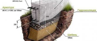
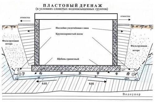
The drainage system for a block foundation (as for any other) begins with filling the foundation pit with crushed stone, and it is recommended to fill not only the perimeter, but also retreat at least another meter in all directions. Then the foundation itself is laid and thoroughly waterproofed, but then there are differences. Depending on the level of soil watering (the indicator is taken as an average for the entire annual cycle), the drainage system can be equipped with a meter-long plume of crushed stone and compacted sand, or it can be created in the form of a highly layered cake, which includes: geotextiles, crushed stone and soil. The internal part of the drainage is a crushed stone fill with an equipped pit, much lower than the level of the fill itself, from which water is removed gradually and naturally, or using a submersible pump.
Advice: It is best to do internal areas with slopes of the main level of the fill towards the walls in order to avoid watering the entire surface and prevent washing out of the fill material.
During periods of frost and winter, leaving the foundation without heating (half-ready), slopes will allow the foundation to maintain its perimeter integrity without the formation of tears and ice on the seams.
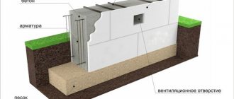
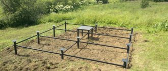
A simplified version of installing a slab foundation
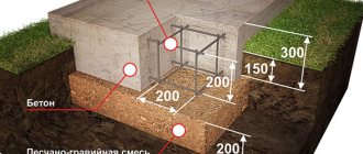
Floating foundation diagram.
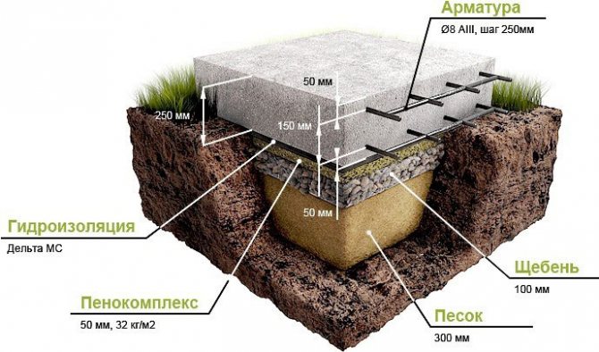
A drainage system is created in a pre-dug pit. Then crushed stone 40-60 mm thick is laid in layers at the bottom of the pit, compacted and gradually created a layer at least 200 mm thick. Crushed stone is poured with a layer of concrete 4 cm thick. After hardening, the concrete is coated with a bitumen primer, ensuring waterproofing of the foundation.
Then formwork is made around the perimeter so that it is approximately 15 cm higher than the level of the future foundation slab. Two metal meshes are fixed parallel to the formwork. Additional reinforcement is made on the lower mesh using metal rods. To quickly fill the formwork with concrete, it should be ordered in advance and delivered to the pouring site by a vehicle equipped with a mixer. Once the concrete has hardened sufficiently, a tarp or dark sheet should be laid over the foundation.
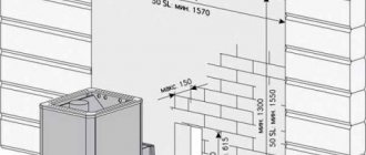
Multi-level drainage around the foundation
Proper foundation drainage is carried out based on the soil adjacent to the structure and the general slope of the land. The only thing that is a relatively constant value is the quantitative and qualitative composition of the drainage mixture.
Multi-level drainage of a deep-set foundation is arranged according to the principle of different distances of levels from the immediate wall according to the following principles: - the higher the drainage level, the farther it is from the wall; - the deeper the level, the wider the drainage channel and the greater its capacity; — there may be no connections between the levels if there is no need for emergency drainage of the mass water flow.
Separately, it is necessary to talk about the special case of drainage of a deep monolithic or block foundation - a storm sewer (storm drain), which is designed and created separately from all levels of drainage of the foundation walls. A very important detail regarding the storm drain is its complete autonomy and isolation from the classic foundation drainage.
Submersible and surface pumps
Drainage pumps are designed for pumping out settled water from wells. They are used if water does not flow out of the receiving well by gravity.
When choosing a pump, you should consider its performance. The peculiarity of this type of pumps is their good performance and low pressure generated. Unlike conventional analogues, this type of pump has a cutting device that allows pumping out water containing solid fibrous compounds. Therefore, when purchasing a pump, pay attention to the size of the particles that it is able to grind. This data is available in the accompanying documentation.
All elements of drainage pumps are made from materials that are resistant to corrosion. To ensure independence from the state of the electrical network, they are sometimes combined with gasoline or diesel engines.
Submersible pumps are used for pumping water with a low content of sand and silt. They must have a float level sensor that turns on when a certain water level in the well is reached. Additionally, a thermal relay can be installed in them as an element of protection against overheating. Pump capacity from 5 to 25 m3/h.
Surface pumps are installed near wells. They allow you to pump out water from a depth not exceeding 8 m. When choosing a pump of this design, it is necessary to take into account its performance, the amount of pressure generated and the vertical distance from the pump installation location to the water level in the well. The pump is protected from overheating by a fan that blows over it.
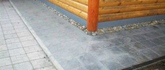
Slab Foundation Drainage
Drainage of a slab foundation involves drainage along the perimeter of a monolithic solid-fill concrete slab and over the entire area of its base. Drainage, as usual, is carried out downhill with access to an inspection or drainage well, from which water can be supplied for filtration to treatment facilities. The drainage distance from the foundation is limited only by the width of the slab itself, which acts as a blind area. It must be said that drainage of the base of the slab is based on careful preparation of the soil (excavation, compaction and strengthening), laying a drainage substrate made of geotextile (at least 300 grams per square meter), a layer of sand and crushed stone. If the area of the future filling is large, then rubble can act as a support and drainage at the same time.
In this case, the drainage of the foundation of the house will look like this: - deeper excavation with a slope in one direction (the slope in the same direction as the main level of the land plot seems quite logical); — laying geotextiles (not only on the bottom, but also on the walls of the pit); — butovka (butting) using tamping mechanisms; - filling with crushed stone.
Just like the drainage of a pile foundation, the drainage of foundation structures with deep laying of individual elements can be modeled as a system of channels located inside the foundation itself. But then the biggest difficulty will be designing the possibility of bringing drained water to the surface or connecting this system with external drainage using pre-calculated embedded passages in the form of steel tubes.
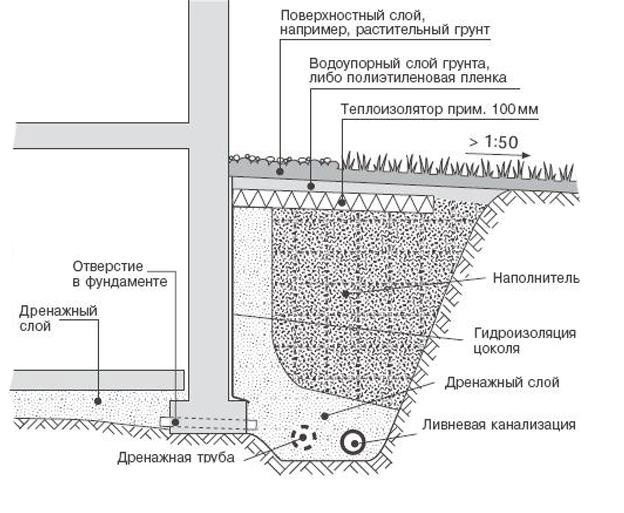
Wall drainage technology
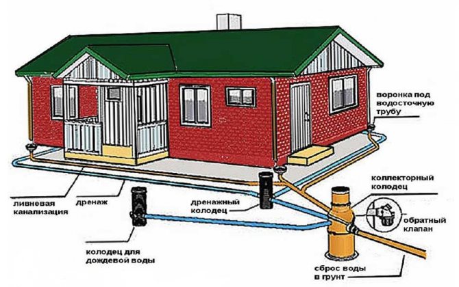
Linear drainage diagram around the house
This system is most common in private housing construction. It is required for almost all objects, since it allows you to avoid troubles during heavy precipitation and in the spring, when the top layer of soil is abundantly moistened. In addition to the above SP, when laying it is also necessary to be guided by SNiP 3.07.03-85* and SNiP 3.05.05-84.
Wall drainage can be done in two ways, the choice between which depends on the type of foundation:
- linear (according to the joint venture, the effective drainage depth is up to 4-5 m) along the perimeter of the blind area for strip foundations;
- layered at the level of the sand cushion under the foundation slabs (according to the standards, the linear type must also be included).
Reservoir drainage under slab foundation.
The following describes the technology for the most common linear installation.
Installation requirements
When designing a drainage system, it is necessary to take into account the requirements for its location:
- laying depth of wall drainage - 30-50 cm below the base of the foundation;
- slope towards the catchment area - 0.02 (for every meter 2 centimeters);
- the maximum distance from the outer edge of the foundation strip is 1 m.
Before laying pipes, determine the upper and lower points of the system. First, they determine the collection point (lower) from which water will be drained from the drainage. After determining this point, calculate the top elevation taking into account the length of the pipes and their required slope.
Materials and tools
To get the job done you will need the following tools:
- bayonet and shovel shovels;
- pick;
- electric or pneumatic hammer drill;
- building level and tape measure;
- wheelbarrow or cart for transporting soil;
- manual rammer or vibrating plate.
To arrange the drainage system you will also need the following materials:
- pipes;
- crushed stone or gravel;
- sand;
- geotextiles;
- polypropylene rope.
Pipes for drainage measures, according to regulatory documents, can be made of asbestos cement, ceramics or plastic. Crushed stone should be selected with a fraction (grain) size of 20-40 mm. The sand used is the same as for backfilling (medium-grained or coarse-grained).
How to make foundation drainage
Any drainage system is a set of water pipes of different sizes and capacity. But, what is much more important, all these channels are in a pragmatically calculated system, which allows you to achieve a certain effect. Drainage under the foundation is always done with a reserve, because it depends on too many variables and factors that appear in relation to soil types, preparatory work carried out, etc.
Above we described some general principles for performing work on different types of foundations. If everything that has been said seems too complicated, seek help from specialized specialists, because a dismissive attitude towards this class of work is unacceptable.
Drainage systems and their features
Slab foundation drainage is laid in trenches previously dug in the foundation pit.
Drawing of the future drainage system.
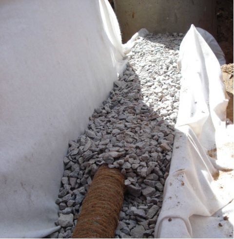
Such trenches are dug across the perimeter. The bottom of the trenches is lined with geotextiles, on top of which crushed stone is poured. Double-layer polyethylene pipes are laid on the crushed stone. Holes are made in the upper part of the cylindrical surface of the pipes to allow water to penetrate into them.
It is advisable to purchase pipes that already have holes. The pipes are laid with a slope (1 cm per 1 m of trench length) towards the perimeter, covered with a layer of crushed stone 20-25 mm thick and covered with geotextile lite on top. This will prevent any debris from getting into the pipes.
Along the perimeter of the rectangle of the future foundation, trenches are also dug for drainage. To do this, the dimensions of the area are increased by approximately 1.5-2 m. These trenches are also prepared for laying pipes. The pipes are laid with a slope from the middle of the side of the rectangle in both directions. Hermetically sealed wells are installed at the corners of the slab.
Lack of drainage: what are the consequences?
Drainage of a strip foundation is extremely important, because in its absence irreparable consequences are possible: - erosion (washing out) and subsidence of the soil under the foundation; — destruction of the integrity of the material due to systematic contact with moisture; — violation of construction connections between individual elements of the foundation structure.
This is far from a complete list of what can happen, but any of the listed violations is more than enough for the entire structure to begin to collapse.
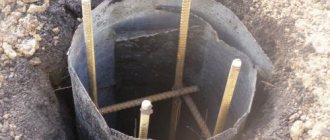
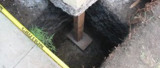
Drainage wells
Wells are made of polymers, they can also be created from concrete rings. They are rotary (or viewing), water receiving and absorption (filtering). Rotary wells are available in any such system. They must be installed in places where drainage pipes turn sharply and every 30-50 m in straight sections, which are intended for washing them and inspecting the entire system. Image 4 shows one of the options for a drainage well.
The wells are covered with cast iron or plastic hatches. However, nowadays cast iron hatches are practically not used. They are replaced by hatches made of other materials, mainly plastic. Plastic hatches can be installed anywhere except highways. Such hatches are not afraid of temperature changes, are light in weight and have a long service life. They are much cheaper than cast iron and do not form sparks upon sudden contact with metal. Their main advantage is that they are not accepted at metal collection points.
Drainage and its additional systems
- Polymer pipes have greatly simplified drainage work. They are made from polyvinyl chloride (PVC), polypropylene (PP) and low-pressure polyethylene (HDPE) and high-pressure polyethylene (LDPE). They range in diameter from 50 to 300 mm. Manufactured using a special method (extruded), they can be used for 50 years.
- Pipes should usually have slotted or round holes and can be laid to a depth of up to 3 m.
- The plastic gutter has steel nozzles and a grid. In terms of withstanding loads, it meets the strength requirements and is quite suitable for individual use.
- Storm water inlets are mainly cast iron products. They have connections to stormwater systems. They are used near the house and on open surfaces.
The construction of even a small house on a foundation that is a solid monolithic slab, despite its strength, is fraught with certain dangers. And this situation is mainly determined by the quality of the independently completed drainage system.